

Inside NTFS: Dissecting the Boot Sector– PART1
Hard Disk Geometry and Physical Structure
Let’s start with a basic concept here; knowing about disk geometry will help you to understand some of the values in a file system. The goal of this section is to obtain a conceptual understanding of what is going on inside. Schematic diagrams of hard disk are illustrated in ‘Figure 1’ to ‘Figure 4’.
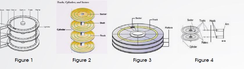
Hard disks contain one or more circular platters that are stacked on top of each other and spin at the same time. Inside the disk there is an arm that moves back and forth, and it has a head on the top and bottom of each platter that can read and write data, although only one head can read or write at a time.
A low-level format is performed on the blank platters to create data structure for tracks and sectors. A track is a circular ring that goes around the platter. It is similar to a lane on a running track so that if you go around the entire circle, you will end in the same location that you started. Each track on the hard disk is given an address from the outside inward, starting with0.
For example, if there were 10,000 tracks on each platter, the outside track of each platter would be 0, and the inside track (nearest the center of the circle) would be 9,999. Because the structure of each platter is the same and the tracks on each are given the same address, the term cylinder is used to describe all tracks at a given address on the platters.
For example, cylinder 0 is track o on the top and bottom of all the platters in the hard disk. The heads in the disk are given an address so that we can uniquely identify which platter on which side of the platter we want to read from or write to.
Each track is divided into sectors, which is the smallest addressable storage unit in the hard disk and is typically 512 bytes. Each sector is given an address, starting at 1 for each track.
Therefore, we can address a specific sector by using the cylinder address (C) to get the track, the head number (H) to het the platter and side, and the sector address (S) to get the sector in the track.
I wrote a utility ‘PhysicalDiskProp.exe’ to display the physical disks’ properties that are attached to the system including hard disks and any removable storage media. Below is an illustration of its output:
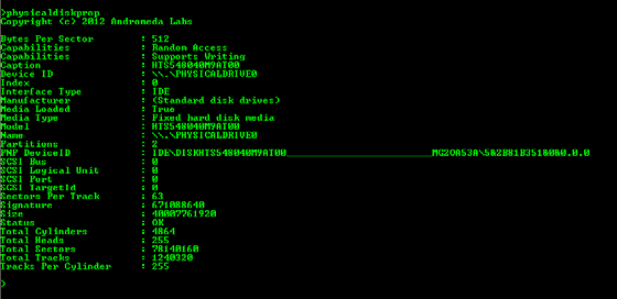
Please note that the total disk capacity can be defined as:
Total Disk Capacity = Total Cylinders * Total Heads * Sectors per Track* Bytes per Sector
40007761920 = 4864 * 255 * 63 * 512
Types of Sector Addresses
The CHS addressing scheme sounds good, but it has proven to be too limiting and is not used much any more. The original ATA specification doesn’t allow for storages more the 504 MB.
To work around the 504MB limit, new BIOSes were developed that would translate the address ranges that they liked to the addresses that the ATA specification liked. The translation process does not work for disks that are larger than 8.1GB.
To overcome the 8.1GB limit associated with translation, the CHS addresses were abandoned, and Logical Block Addresses (LBA) became standard. LBA uses a single number, starting at 0, to address each sector. With LBA, the software does not need to know anything about the geometry; it needs to know only a single number.
The conversion algorithm from CHS to LBA is:
LBA = (((CYLINDER * heads_per_cylinder) + HEAD) * sectors_per_track) + SECTOR – 1 Where you replace CYLINDER, HEAD, and SECTOR with the respective CHS address values. For example consider a disk that reported 16 heads per cylinder and 63 sectors per track. If we had a CHS address of cylinder 2, head 3, and sector 4, its conversion to LBA would be as follows: 2208 = (((2 * 16) + 3) * 63) + 4 -1
Boot Process
To simplify matters, when a machine is powered on, the CPU reads instructions from a specific location in the read-only memory, known as (ROM). After probing the hardware configuration, the CPU searches for a device that contains the boot code. If it finds such a device, its boot code is executed, and the code attempts to locate and load a specific operating system.
The process after a bootable disk is found is platform specific. As an example, we will take a brief look at the boot process of a Microsoft Windows system. When the system is powered on, the CPU read instructions from Basic Input/Output System (BIOS), and it searches for the hard disks, CD drives, and other hardware devices that it has been configured to support.
After the hardware has been located, the BIOS examines the floppy disks, hard disks, CDs in some configured order and looks at the first sector for boot code. The code in the first sector of a bootable disk causes the CPU to process the partition table and locate the bootable partition where the Windows Operating System is located. In the first sector of the partition table, there is more boot code which locates and loads the actual operating system’s files.
About The Author

Amr Amin, Chief Architect, IT Compliance Andromeda Labs